


Concrete screw with hexagon head and large disc W-BS/S
Concrete screw W-BS, type S w. la. washer ST galv.
ANC-(W-BS/S)-(A2K)-WS15-155-185-10X240


Register now and access more than 6,000 products
- Extremely flexible to use due to three anchoring depths
- Fastening can be adjusted up to twice after installation, for example in order to align railings or anchor plates (please refer to the assembly guide)
- Very high loads
- Smallest spacing and edge distance thanks to very low expansion effect
- Very fast and easy assembly and immediately load-bearing
European Technical Assessment ETA-16/0043 for individual fixing point, option 1, cracked and uncracked concrete:
- Static and quasi-static effects
- Seismic exposure, performance categories C1 and C2
- Fire resistance R30, R60, R90, R120
DIBt National technical approval/general type approval Z-21.1-2075 as bonded screw anchor for anchoring in concrete
- Use in combination with injection mortar WIT-BS as bonded screw anchor WIT-BS
- In reinforced and non-reinforced and cracked and uncracked concrete C20/25 to C50/60
From size 8, we recommend the use of a suitable tangential impact screwdriver for installation. The recommended maximum nominal torque must be observed.
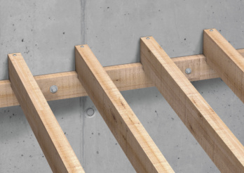 Wooden structures
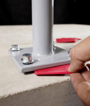
Adjustment - subsequent aligning possible.
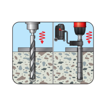
Create the drill hole
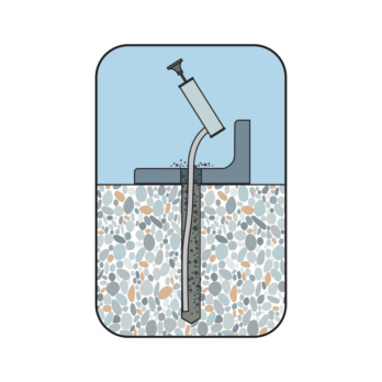
Clean the drill hole
Place screw
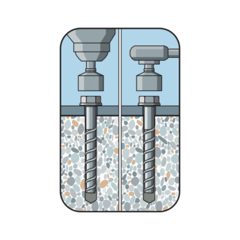
Screw in the screw
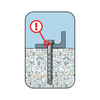
Considered installed when the head is close fitting
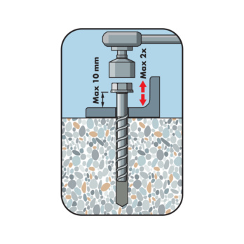
Screw out the screw max. 2x each by max. 10 mm. Underlay. Screw in
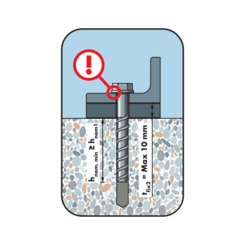
Considered installed when the head is close fitting. Lining max. 10 mm. The required embedment depth must be maintained as a minimum
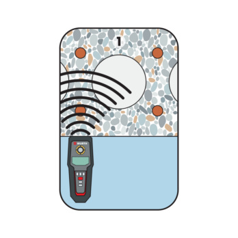
Locate the tensioning strand
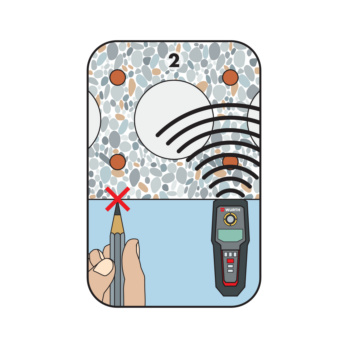
Mark the tensioning strand and locate the next one
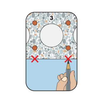
Mark the tensioning strands. Specify the drilling range
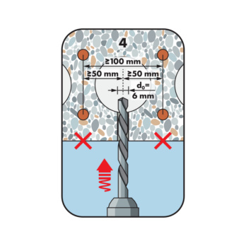
Create the drill hole. Observe spacing
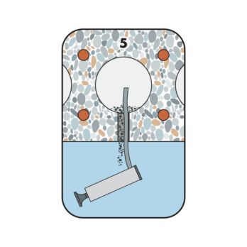
Clean the drill hole
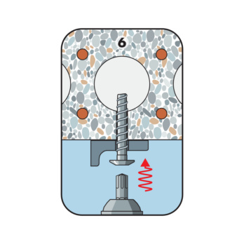
Screw in the screw
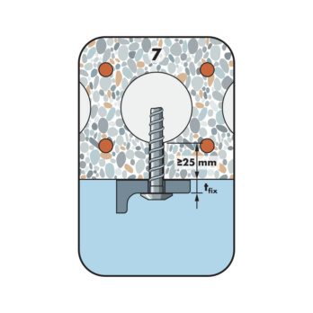
Considered installed when the head is close fitting. Observe the embedment depth/mirror thickness
European Technical Assessment ETA-16/0043 for individual fixing point, option 1, cracked and uncracked concrete:
- Static and quasi-static effects
- Seismic exposure, performance categories C1 and C2
- Fire resistance R30, R60, R90, R120
DIBt National technical approval/general type approval Z-21.1-2075 as bonded screw anchor for anchoring in concrete
- Use in combination with injection mortar WIT-BS as bonded screw anchor WIT-BS
- In reinforced and non-reinforced and cracked and uncracked concrete C20/25 to C50/60
Individual fixing point with approval:
Normal weight concrete C20/25 to C50/60 (cracked and uncracked concrete)
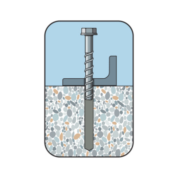
Especially suitable for fixtures in wooden construction applications in concrete:
- Mounting of e.g. support beams, sleepers, inferior purlins, canopies, wooden substructures, etc.
- Fastenings under seismic conditions in earthquake areas
- Fastenings under exposure to fire
W-BS/S (galvanised steel) may only be used in dry indoor room conditions
For use in concrete < C20/25 and pressure-resistant natural stone (without approval)
Anchor size | 10 mm |
Anchor length (l) | 240 mm |
Attachment height (t fix 1) | 185 mm |
Attachment height (t fix 2) | 165 mm |
Attachment height (t fix 3) | 155 mm |
Thread diameter | 12 mm |
Nominal drill-bit diameter (d 0) | 10.0 mm |
Drill hole depth (h 1.1) | 65 mm |
Drill hole depth (h 1.2) | 85 mm |
Drill hole depth (h 1.3) | 95 mm |
Embedding depth (h nom1) | 55 mm |
Embedding depth (h nom2) | 75 mm |
Embedding depth (h nom3) | 85 mm |
External drive | WS15 |
Material | Steel |
Surface | Zinc plated |
Washer diameter | 44 mm |
Through-hole in the component to be connected (d f) | 14.0 mm |
Head type | Hexagon head |
Type description | W-BS type S |
| Performance data in concrete - fixing point according to ETA-16/0043 | |||||
| Anchor size [mm] | 10 | ||||
| Length of anchor in drilled hole | hnom [mm] | 55 | 75 | 85 | |
| Admissible centric tension load1) on an individual anchor without the influence of the edge distance | Tensile zone (cracked concrete C20/252), s ≥ 3 hef c ≥ 1.5 hef) | Nperm. [kN] = C20/252) | 4,3 | 8,0 | 9,6 |
| Compressive zone (non-cracked concrete C20/252), s ≥ 3 hef c ≥ 1.5 hef) | 5,7 | 9,5 | 11,9 | ||
| Admissible shear load1) on an individual anchor without the influence of the edge distance | Tensile zone (cracked concrete C20/252), c ≥ 10 hef) | Vperm. [kN] = C20/252) | 4,8 | 15,9 | 16,2 |
| Compressive zone (non-cracked concrete C20/252), c ≥ 10 hef) | 6,8 | 16,2 | 16,2 | ||
| Permissible bending moment | Madm [Nm] | 26,7 | |||
| Admissible load under seismic activity performance categories C1 and C2 see European Technical Assessment ETA-16/0043 | C1 | x | x | ||
| C2 | x | ||||
| Admissible load when exposed to fire (R30, R60, R90, R120), see European Technical Assessment ETA-16/0043 | |||||
| 1) The partial safety factors of the resistances yM regulated in the evaluation/approval and a partial safety factor of the effects of γF = 1.4 have been taken into account. For a combination of tensile and shear loads, for the influence of the edge distance and anchor groups please see the appropriate guidelines e.g. DIN EN 1992-4. 2) The concrete has normal reinforcement. Higher values are possible for higher concrete strengths. | |||||
| Installation parameters in concrete | ||||
| Anchor size [mm] | 10 | |||
| Nominal length of thread engagement | hnom [mm] | 55 | 75 | 85 |
| Minimum axis distance | smin [mm] | 50 | ||
| Axis distance | scr,N [mm] | 129 | 180 | 204 |
| Minimum edge distance | cmin [mm] | 50 | ||
| Edge distance | ccr,N [mm] | 64,5 | 90 | 102 |
| Minimum member thickness | hmin [mm] | 80 | 90 | 102 |
| Nominal drill ∅ | d0 [mm] | 10 | ||
| Diameter of cutting edges ∅ | dcut ≤ [mm] | 10,45 | ||
| Drill hole depth | h1 ≥ [mm] | 65 | 85 | 95 |
| Through hole in the component being connected | df ≤ [mm] | 14 | ||
| Width across flats | [mm] | WS15 | ||
| Washer diameter | dw [mm] | 44 | ||
| Washer thickness | tw [mm] | 4 | ||
| Screw-head height | hn [mm] | 10 | ||
| Max. rated torque of tangential impact screwdriver | Timp,max [Nm] | 400 | ||
Würth Catalogue (1)
Datasheets (1)
CAD data (available after login)
Certificates/ Documents (0)

Last viewed

Specially fused alumina sanding tip, pink

7-pin socket 12 V With cut-off contact for rear fog light

Metric double-end flare-nut wrench Bi-hex with POWERDRIV®

3/8 inch impact socket wrench insert hexagon, metric, short

Voltage protective glove For working voltages up to 1,000 V/AC

Drilling screw, hexagon head with sealing washer pias®

MFD-S multi-purpose drill bit with straight shank

Arizona® Perfect soft vehicle dry abrasive paper For all paint repair work with intermediate and fine sanding

Knife blade, L-shaped, toothed

Countersunk head screw with hexagon socket ISO 10642, A4-070 stainless steel, plain
